The T-35 Heavy Tank plan was the product of Section AVO-5 of the tank design bureau located in the Leningrad "Bolshevik" Factory. Their directive was to develop a large and heavily armed break-through vehicle for the Soviet Infantry. Headed by N.V.Barykov, who had also assisted the combined German/USSR tank design team before it was broken up in 1934, the design section produced drawings and the first prototype T-35-1 Heavy Tank in August of 1932. A second prototype of slightly different design, the T-35-2, was completed the following year and after extensive changes were made the series production of the T-35 began in early 1934 with the T-35A model. Six were produced in time to participate in the Moscow November 1934 parade with an additional four machines completed and sent to the Army that same year.
More improvements were necessary during the AFV's short production run, including the addition of heavier armor, redesigned conical turrets, and an upgraded drive train. But even these changes could not alter the fact that the vehicles were impossible for one man to command, they were too slow, and they remained mechanically unreliable when the two Regiments of the 34th Tank Division drove from Grudek-Yagellnoskin into war against the German Reich in June of 1941. By the end of July both the 67th and 68th Regiments of the Division had lost all their vehicles, most to mechanical breakdowns. This was not a successful display of Soviet armored might and the T-35 design was finally abandoned by the end of the year. Between its birth in 1933, and its withdrawal from the field of battle in 1941, there were only 61 vehicles constructed.
 Picture 1:
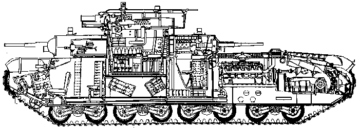
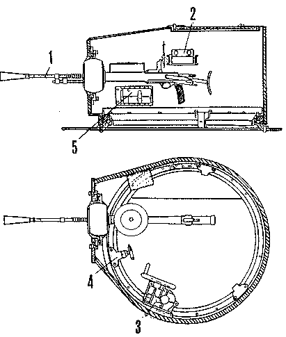
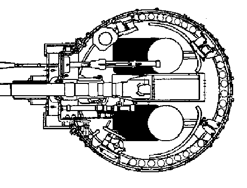
The T-35 was a monster of a tank that weighed over 110,000lbs (50,000kg) and included five turrets on two tiers manned by a crew of 11. The large centrally located main turret mounted a 76.2mm cannon with a secondary 7.62mm DT machine gun to the right. Two of the other four turrets contained a 45mm gun with coaxial DT MG while the other diagonal pair mounted a DT MG in each. The driver sat at the very front and to the left in the tank. Just behind him, to either side, were the front two turrets- the medium two-man 45mm gun turret to his right and the one-man MG turret directly behind. The overworked commander sat on the right in the main turret and was accompanied by the gunner on the left, loader/engine mechanic at the rear and radio operator just behind the commander. A bulkhead separated the main turret fighting compartment from the front and rear turret areas and there was no access from one compartment to the next, except to climb out of the vehicle and then reenter. In the rear turret compartment the larger 37mm turret was on the left side of the hull and the MG turret on the right. A firewall behind the last two turrets separated this section from the large engine and transmission compartments at the rear of the AFV. This is a cleaned version of a drawing of a T-35A tank from Modelist-Konstruktor Magazine (Armor Collection 2-95) illustrating some of the main interior components and their locations. The driver's seat is at the far left in the picture (bow) which also shows the outline of the far 45mm turret on his right. Some detail of the one-man MG turret on this side of the hull is included. Although the medium 45mm gun turrets included a rotating partial turret floor for the two crew members, the small one-man MG turrets did not. Up in the main turret you can see the seat for the gunner on our side and a tall ammo carousel is bolted under the seat (the commander's seat on the far side of the turret also had one). At the rear of the turret ring is the lower seat for the loader/engine mechanic which effectively hides the radio operator's seat next to it. This main turret had a suspended full revolving floor with access panels to retrieve ammo stored underneath. Behind the main turret compartment (to the right in the drawing) is the rear medium 45mm gun turret, now on our side of the hull, with hanging seats and partial floors for the gunner and loader inside. Behind the firewall are the engine, transmission, radiators and final drive.
Picture 2:
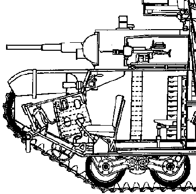
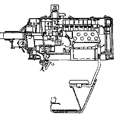
We'll begin our examination of the T-35 in the bow of the long AFV, in the driver's area, with this crop from the previous T-35A drawing. The driver steers the vehicle with traditional twin levers mounted on the floor at either side of his seat and he uses three pedals at his feet- clutch, accelerator and reserve. The seat is substantially padded with horse hair and covered with leather. It is adjustable in height and can slide forward or back. Directly in front of the driver are instrument panels and a large hinged vision flap which includes a vision slit with protection to the driver with thick, removable, glass blocks ("triplex"). To his lower right is a large slanted floor bin storing 45mm ammo for the medium turret further to his right and just behind him is a small MG turret with racks of 7.62mm MG drum ammo behind the machine gunner's seat and along the hull wall. The padded seat for the MG turret is also adjustable in height, covered with leather, and folds up against the bulkhead when not in use. Notice the floor is raised above the belly plates some distance to allow a space for control rods and electrical conduits under the floor.
Picture 3:
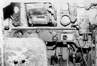
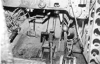
This interior photo of the sole surviving T-35 (in the Kubinka Museum) provides a tantalizing view of some the driver's area of a vehicle with much of the interior equipment missing. The driver's seat back is to the lower left in the photo with his primary vision port flap directly in front. Over-head and out of view is the wide two-piece hatch allowing entry down into his position. The MG turret overhang directly behind him blocks the opening of the hatches unless the turret is rotated at least 40 degrees to the left. The main instrument panel stretches across in front of the driver and two small sub-panels are located on either side of his forward vision flap. The large hole on the left of the main panel was for the tachometer and to the right are empty spaces for the electrical system's ammeter and voltmeter. The rectangular boxed opening housed the magneto starter switch and to the left was the main electrical power switch. To the left of the box opening of the magneto starter switch and above it is the gas feed selector. The horn button is the largest button on the lower part of the panel. The two smaller panels framing the viewing flap contained temperature , pressure and level gages for oil, water and fuel, one of which is still visible in the left panel. The pedals on the floor include a clutch, an accelerator and a foot pump lever for pressurizing air for starting the engine with the mechanical starter instead of the electric starter system. A reserve spark adjustment lever is located to the far right in the long instrument panel and below that is the knob for the gear shift handle. Above the spark adjustment lever is a rectangular box bolted to the front armor plate which housed a large vehicle compass (which has been removed and blanked off). At the far right can be seen just the edge of the white floor mounted ammo rack for 45mm rounds. This photo was taken from the MG turret area directly behind and to the left of the driver/mechanic's seat.
Picture 4:
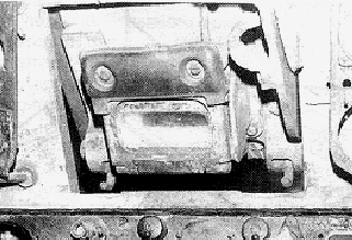
A close-up view of the driver's forward vision flap shows it is partially open. It is hinged at the top and a triplex glass block is installed in the holder that covers a thin vision slit in the flap. A large leather covered forehead bump pad is mounted above the glass blocks. The vision flap can be locked closed by the handle on the right and the twin catch hooks are seen at the bottom of the flap. The interior walls and ceilings of the fighting compartments are all painted white and the floors are covered with black rubber mats. Out of view here to the left of the driver is a hull side vision flap which is also protected with triplex glass blocks. There was no direct view for the driver to the right of the tank and he relied on the commander, via a telephone system, for general movement instructions. Due to the height of the front fenders to either side of his open viewing flap, the driver had a very narrow field of view, even opened completely up.
Picture 5:
This is the view looking toward the floor of the driver's area, showing the three pedals we mentioned earlier. In clearer view now is the gear shift lever with round handle and its gate on the floor just to the right of the seat. Just forward of the shift gate can be seen the end of the lower of two compressed air cylinders, mounted in the forward wall of the compartment. These are the 150psi air storage tanks that were used to mechanically assist start the engine, particularly in cold weather. The main twin steering levers that control the lateral clutches and brakes are also now seen to either side of the seat with their black rubber handle grips. More of the 45mm ammo rack for the two-man medium turret to the driver's right is seen at the far right edge of the photo.
Picture 6:
The DT machine gun turrets were fairly simple affairs, identical to the ones used in Russian T-28 tanks, and very similar in design to others in use in British AFVs of the time. The drawing shows the DT MG in its ball mount, allowing limited all around elevation and traverse to 30 degrees except in depression, which was -20 degrees. The turret was manually traversed by the gunner using a gear and hand wheel seen to the immediate left of the gun in the lower drawing (3). A view slot and protective glass block is located in the left wall of the turret (2) and two spare vision blocks are stored in a small box to the right of the gun (5). The gunner typically sat in a foldable seat bolted to the belly plates of the AFV and peered through the sights of his MG through a small hole in the ball mount. His ammo drums were stored in racks stacked along the hull wall on his left (or right, in the rear MG turret). A large hatch covered the rear of the turret roof and hinged forward. Exiting the vehicle through these hatches was very difficult and required the tanker to hoist himself up and out with his arms only, exposing him to enemy fire in the process.
Picture 7:
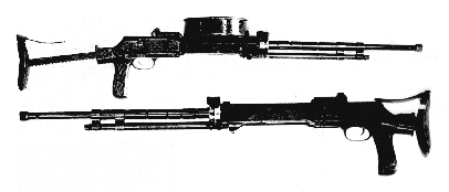
The DT light machine gun was the tank version of the very simple DP LMG, designed by Vasiliy Alexeyevich Degtyarev, which first appeared in 1926 (T stands for "Tank" while P stands for "Pekhotniy", or Infantry). The DT version was first supplied in AFVs in 1929 and, like the DP, was a gas-operated, drum-fed 7.62mm (.30in) weapon which was very reliable and used in service until 1947 by the Red Army. The DT Model 1929 operating mechanism was identical to the DP, with the primary modifications to the weapon being the replacement of the long wooden stock with a retractable metal type with wooden pistol grip and a different, taller, drum ammo magazine which held 60 rounds in two layers. When mounted as a tank MG, a separate optical sight was used on top of the receiver. This illustration shows the metal butt stock both in the extended and shortened positions. The ammo drum looks similar to the British Lewis type, but this drum's outer casing remains stationary while only the inner ring revolves around the spindle to deliver rounds into the receiver. This fully automatic weapon had an effective rate of fire of 120 rounds per minute at a velocity of around 2755fps (839mps). Maximum range was 880yds (800m) and a total of 10080 rounds of MG ammo were said to be carried in the T-35 to service the five to seven DT machine guns on board.
Picture 8:
The early T-35 medium turrets mounted the 1932 Model 45mm 20K tank cannon, which was replaced by the Model 1934 with a semi-automatic vertical falling breech in place of the earlier inertia type. The gunner sat to the left of the weapon on an adjustable height seat with the loader on the right of the gun, responsible for operating the coaxial DT MG on that side of the turret. The guns could elevate from +20 to -6 degrees and rotate a total of about 200 degrees maximum before hitting stops that kept them from hitting the higher central main turret. Both medium turrets were identical in design and layout. Each included two sights for the gunner- a PT-1 periscopic sight in the roof and a TOP telescopic sight mounted in the mantlet. This drawing shows both the elevation and traverse hand wheels for the gunner as well as the partial floor plates under both seats, including the firing pedal for the 45mm weapon. The partial floors are covered with textured black rubber mats. Twenty two 45mm rounds are stored in three racks around the perimeter of the turret, while more are housed in vertical bins underneath the turret and on the hull walls. Over-head hatches in the medium turrets are of the single width type, covering most of the rear of the roof, while the periscope and exhaust fan are mounted in the front half of the roof plate (left and right respectively). Perhaps as many as 226 45mm rounds were carried in the tank and shared by the two medium turrets, half AP and half HE-FRAG. Two vision ports with replaceable glass blocks were mounted on the right and right rear turret wall and small firing port plugs were provided under the vision blocks for submachine gun use.
Picture 9:
This over-head view of the interior of the medium turret shows to better effect the ammo storage around the perimeter of the ring. The model 24 K Model 1924 gun has a long recoil shield on both sides of the breech and a canvas bag below to catch spent shells that were ejected automatically during recoil. The large black areas in the drawing are the partial floors with rubber mats below both seats. Both the gunner's telescopic sight on the left of the 24 K gun and the DT MG on the opposite (loader's) side are clear in the drawing. Also on the loader's side of the turret can be seen the two earlier mentioned vision slits and glass block mounts. Both round seats were padded and covered in leather. They were adjustable in height to allow the crew to ride with their heads out through their over-head hatches. The small turret traverse locking handle is just forward of the turret traverse hand wheel in front of the gunner. This turret plan is very similar to the turret mounted on the BT-5 Fast Tank, minus, of course the BT-5's turret bustle, which was needed for its radio in the Fast Tank. The 45mm gun was included in the T-35 design as the primary anti-armor weapon, while the 76mm gun in the main turret was designed for infantry support and fortification destruction. As with the driver/mechanic's hatches, the medium turret hatches could be blocked closed by the bustle overhang of the main turret if it happened to be located over them at the time. The main turret contained an electrical panel with lights to indicate when the lower turrets were blocked so the gunner could traverse out of their way. This completes our coverage of Part 1 coverage of the T-35 Heavy Tank.
TO SOVIET HEAVY TANK T-35 PART 2
BACK TO AFV INTERIORS HOME PAGE
(c) 2001, AFV INTERIORS Web Magazine